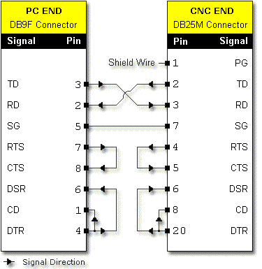
Figure 1. DB9F to DB25M, Null Modem (Crossover)

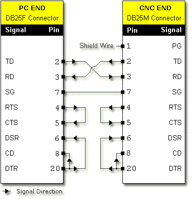
Figure 2. DB25F to DB25M, Null Modem (Crossover)

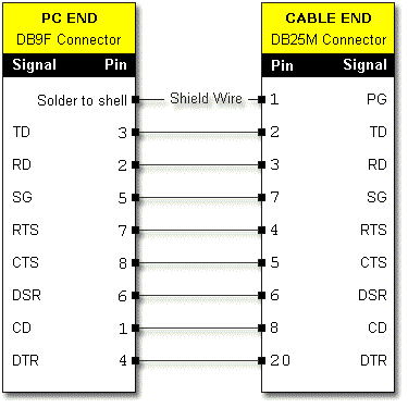
Figure 3. DB9F to DB25M, Straight

Figure 4. RS232C PC 9-Pin
| Pin (DB9) | Signal Function | Label | I/O Type |
| 1 | Carrier Detect | CD | Input |
| 2 | Receive Data | RD | Input |
| 3 | Transmit Data | TD | Output |
| 4 | Data Terminal Ready | DTR | Output |
| 5 | Signal Ground | SG | --- |
| 6 | Data Set Ready | DSR | Input |
| 7 | Request to Send | RTS | Output |
| 8 | Clear to Send | CTS | Input |
Figure 5. RS232C PC 25-Pin
| Pin (DB25) | Signal Function | Label | I/O Type |
| 1 | Protective Ground | PG | --- |
| 2 | Transmit Data | TD | Output |
| 3 | Receive Data | RD | Input |
| 4 | Request to Send | RTS | Output |
| 5 | Clear to Send | CTS | Input |
| 6 | Data Set Ready | DSR | Input |
| 7 | Signal Ground | SG | --- |
| 8 | Carrier Detect | CD | Input |
| 20 | Data Terminal Ready | DTR | Output |
Figure 6. DB25M/RJ45 Modular Adapter (This pinout requires separate null modem adapter, call 805.419.0226 for part number.)
EIA/TIA 561
| DB25 | Wire Color | RJ45 |
| 1 | No Connection | --- |
| 2 | Green | 5 |
| 3 | Yellow | 6 |
| 4 | White | 8 |
| 5 | Brown | 7 |
| 6 | Blue | 1 |
| 7 | Red | 4 |
| 8 | Orange | 2 |
| 20 | Black | 3 |
Figure 7. DB9F/RJ45 Modular Adapter
EIA/TIA 56
| DB9 | Wire Color | RJ45 |
| 1 | Orange | 2 |
| 2 | Yellow | 6 |
| 3 | Green | 5 |
| 4 | Black | 3 |
| 5 | Red | 4 |
| 6 | Blue | 1 |
| 7 | White | 8 |
| 8 | Brown | 7 |
| 9 | --- | --- |